|
|
||||
|
|
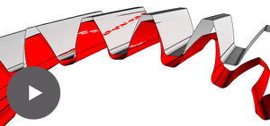
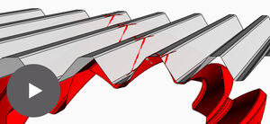
The geometry of two wheels in a pair can be the result of the use of a wide variety of tools. Ultimately, this is the question that always has to be answered: ÂŦdo these wheels really fit together?Âŧ In the case of spur-toothed gears without addendum modification, checking this is relatively straightforward using the parameters. If it involves helical gears, a 2D representation can help. But when it comes to crossed helical gears, it is often only the fully finished wheels that indicate whether or not the calculation was correct. It can prove expensive if it was not correct. Some kind of visualisation is far better, as there are no rejects. This is why we developed our GearViewer software. It displays the rotating wheels in their installation position â with the extra option of also considering axle adjustment errors. 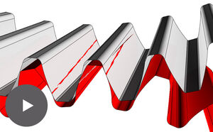 The two wheels make linear contact with each other. In the event of any movement, this contact line wanders over the tooth. It provides information on how correct the geometry of the wheels is, because even the slightest of variations from the specification can lead to the contact line disappearing, becoming deformed or getting out of control in terms of penetration. If, on the other hand, the wheel geometry is correct, the contact line wanders cleanly over the tooth flank. 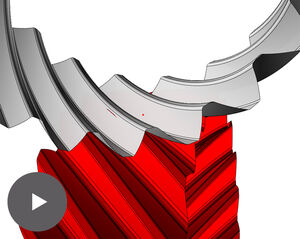 Crossed helical gears have one point of contact. In the event of any movement, this point wanders over the tooth at an angle. Therefore, as in the case of cylindrical gears, information can be gained about how correct the geometry of the wheels is. 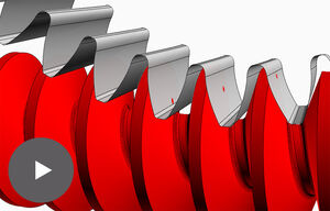 A worm gear (not globoid) and a cylindrical gear make contact with one another at a single point, just like crossed helical gears. Discrepancies relating to contact lines or contact points would become visible immediately. So corrective measures can still be taken before the tools and parts are produced. To achieve this, GearViewer only requires the two profile contours in the transverse section and a few other parameters, e.g. the pitch. The complete display is available in just a few seconds. This procedure can easily be very well integrated into an iterative design process â with this, parameters are modified again and again in turn and their effects checked. 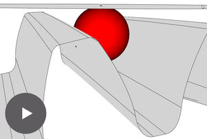 A dimension over balls can be visually checked by GearViewer. The contact points between wheel, balls and the plates of the micrometer screw show immediately, whether everything really fits together. The dimension can be introduced by the user or optionally determined by GearViewer. This works for normal involute gears, but also for profile crowned involute gears, watch wheels, Novikov gears, etc. 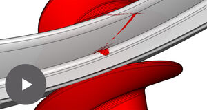 If a worm gear is being produced using a form tool (e. g. a profile cutter), this results in a complex line of contact which can quickly be disturbed if the machine settings are incorrect and this will, therefore, lead to incorrect worm gear geometry. Different machine adjustment errors can be simulated with GearViewer. |
|||
Social Media |
||||
|
© 2000-2026 Irnich Informatik GmbH, CH-2560 Nidau, Impressum, 2012 designed and created by LeiserPublishing GmbH |
||||